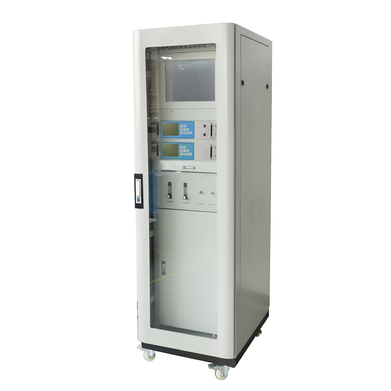
Continuous Emission Monitoring System
Continuous monitoring of SO2, NOx, CO, CO2, O2, HCl, HF, dust, flow, pressure, temperature and humidity.
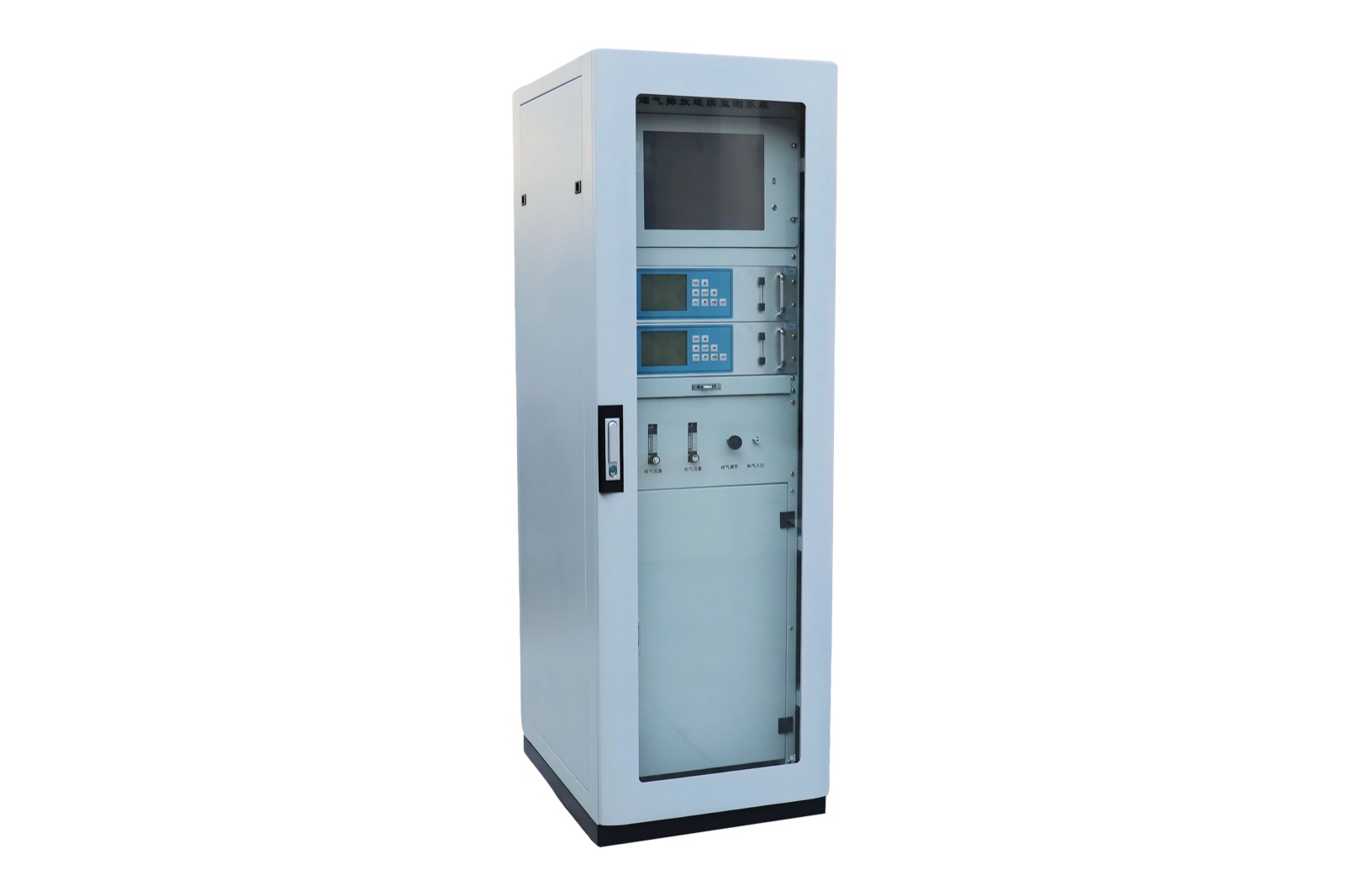
Continuous Emission Monitoring System for environmental monitoring projects
CEMS for continuous monitoring of SO2, NOx, CO, CO2, O2, HCl, HF, dust, flow, pressure, temperature and humidity.
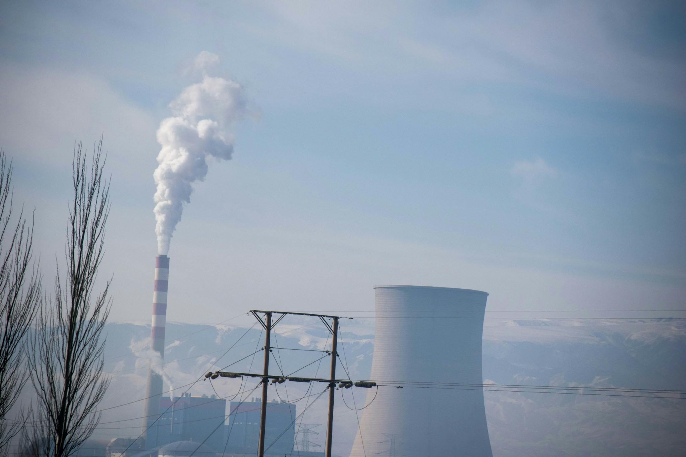
A CEMS is selected when an emission source needs continuous stack monitoring and structured data output. It is commonly discussed for power plants, waste incineration, cement, steel, metallurgy, chemical production and other fixed sources where gas concentration, particulate matter and stack condition values must be integrated.
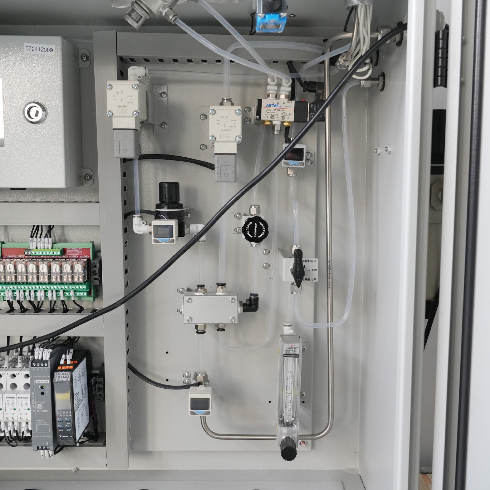
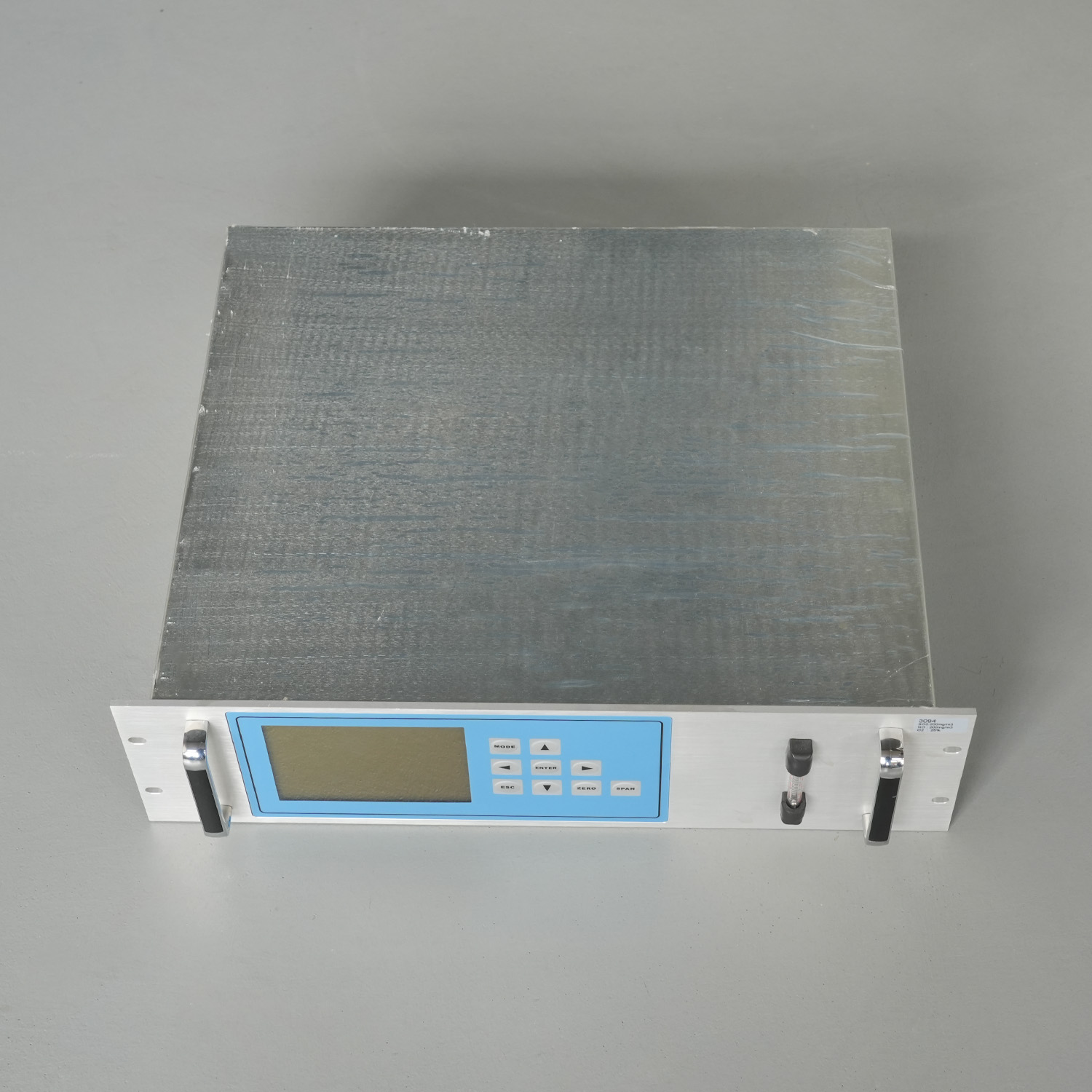
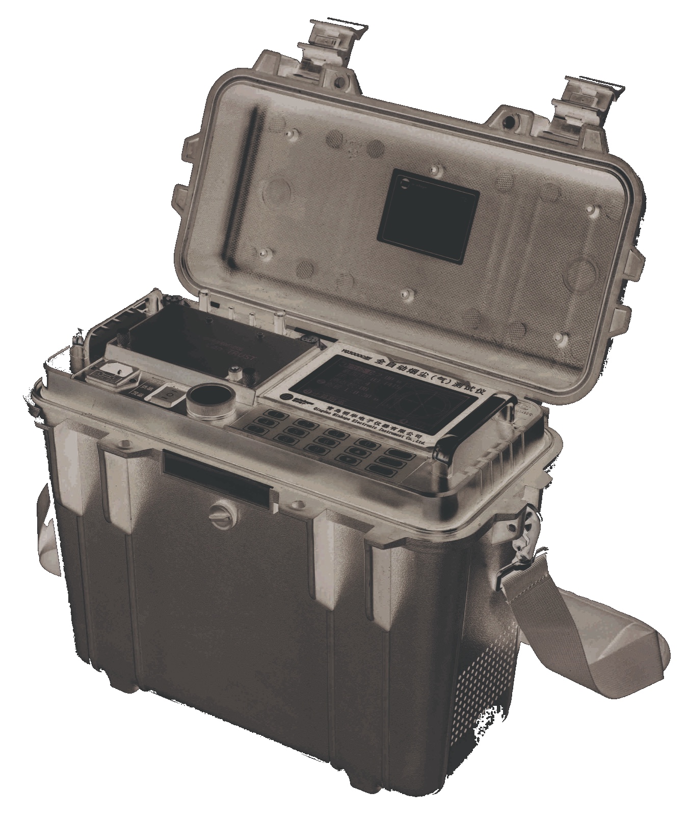
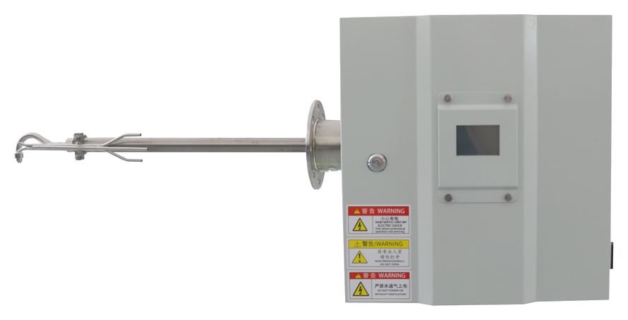
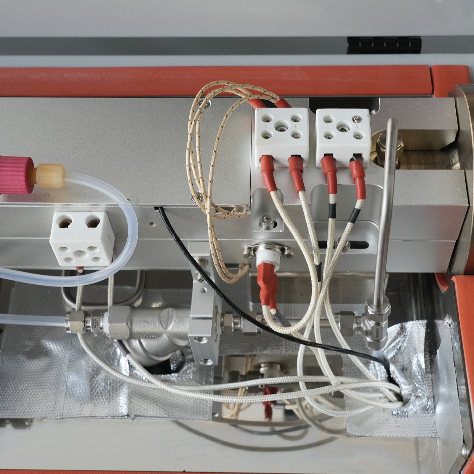
CEMS configuration usually starts with the measured gases and the sample condition. The system may include an extraction probe, heated sampling line, pretreatment unit, gas analyzer cabinet, dust monitor, flow and temperature instruments, data acquisition system, calibration gas interface and shelter or cabinet arrangement.
Technical data for model selection
Review the main measuring range, output interface, operating conditions and configuration notes before quotation.
Huisheng confirms the final model, range and site configuration according to sample condition and monitoring requirement.
| Item | Specification / selection note |
|---|---|
| System | AG-CEMS07II continuous emission monitoring system |
| System composition | Gaseous pollutant monitoring subsystem, particulate matter monitoring subsystem, flue gas parameter monitoring subsystem, data acquisition and processing subsystem |
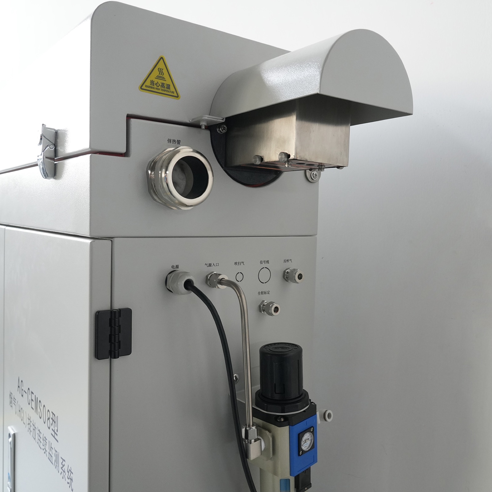
| Sampling unit | Electrically heated sampling probe, heated sampling line and back-flush system |
| Pretreatment unit | Precision filter, compressor condenser, sampling pump, moisture removal tank and flowmeter |
| Analyzer instruments | AG-UVI13 UV-DOAS analyzer and AG-YII21 infrared analyzer are listed in the manual |
| Temperature-pressure-flow model | AG-TFP07 |
| Flow measuring range | 0-40 m/s |
| Flow measurement accuracy | 2% |
| TFP output | 4-20mA and RS485 |
| Pressure / temperature range | Pressure transmitter -5 to 5 kPa or configured; temperature transmitter 0-300 degrees C or configured |
| Humidity meter model | AG-SD07 |
| Humidity range / accuracy | 0-40% VOL; +/-1%FS |
| Humidity output | Modbus RS485 and three-wire 4-20mA options listed |
Configured around the actual monitoring point
Gas sampling, heated line, pretreatment, analyzer and condition sensors work together as one emission monitoring chain.
Stack gas, industrial exhaust, combustion flue gas or source emission points
Temperature, moisture, dust, solids, corrosive components or compound type may affect configuration.
Analyzer, detector, sampler, cabinet, pretreatment and data output can be combined as one product package.
Specifications are prepared according to the selected model and actual project requirement.
Details Huisheng reviews before confirming a model
Huisheng reviews the product model together with the measured medium, target range, sampling condition, installation position and required specifications. This keeps the product discussion tied to the real monitoring point.
Expected concentration or detection level helps determine the model and measurement method.
Temperature, moisture, suspended solids, dust, corrosion or target compound behavior may change the configuration.
Gas sampling, heated line, pretreatment, analyzer and condition sensors work together as one emission monitoring chain.
Stack platform, analyzer cabinet, sampling line and data acquisition location
Communication output, alarm logic and model-specific specifications depend on the selected model.
Monitoring indicators covered by this product series
The final parameter package depends on the selected model, measuring range, sample condition and data output requirement. For many projects, one instrument is part of a complete monitoring point rather than a stand-alone purchase.
SO2
Stack gas indicator used for emission source monitoring and reporting.
NOx
Stack gas indicator used for emission source monitoring and reporting.
CO
Stack gas indicator used for emission source monitoring and reporting.
CO2
Stack gas indicator used for emission source monitoring and reporting.
O2
Stack gas indicator used for emission source monitoring and reporting.
HCl
Stack gas indicator used for emission source monitoring and reporting.
HF
Stack gas indicator used for emission source monitoring and reporting.
Dust
Stack-condition parameter used to interpret emission data and support CEMS configuration.
Flow
Stack-condition parameter used to interpret emission data and support CEMS configuration.
Temperature
Stack-condition parameter used to interpret emission data and support CEMS configuration.
Humidity
Stack-condition parameter used to interpret emission data and support CEMS configuration.
How the product fits into a complete monitoring chain
Most projects connect the product with sample access, conditioning, measurement, data acquisition and reporting. The exact arrangement depends on the site and selected model.
Sampling probe installed on stack
The sample access point determines whether filtration, heating, flow control or preservation is required.
Heated line and moisture control
This part is configured according to the selected model and actual site conditions.
Gas analyzer cabinet
This part is configured according to the selected model and actual site conditions.
Dust, flow and stack condition instruments
This part is configured according to the selected model and actual site conditions.
Data acquisition system and platform interface
Data acquisition, alarm output and communication must match the project platform or reporting requirement.
Where this equipment is usually discussed
Emission applications depend on the stack or duct condition. Gas temperature, dust load, moisture, sampling platform and reporting purpose all influence the analyzer, sampler or complete CEMS configuration.
Applied at fixed emission sources where sample extraction, condition measurement and reporting output must work as one chain.
Configured according to the monitoring point, sample condition, installation environment and expected data use.
Applied at fixed emission sources where sample extraction, condition measurement and reporting output must work as one chain.
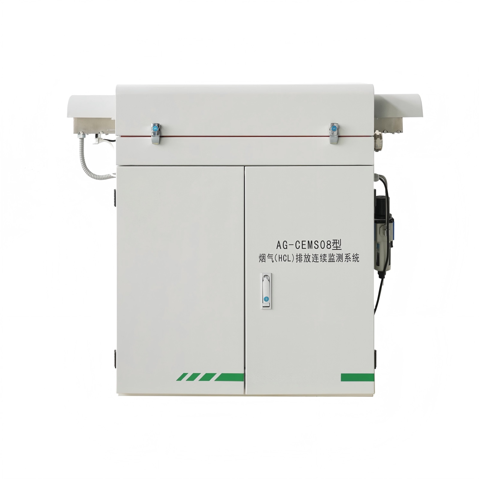
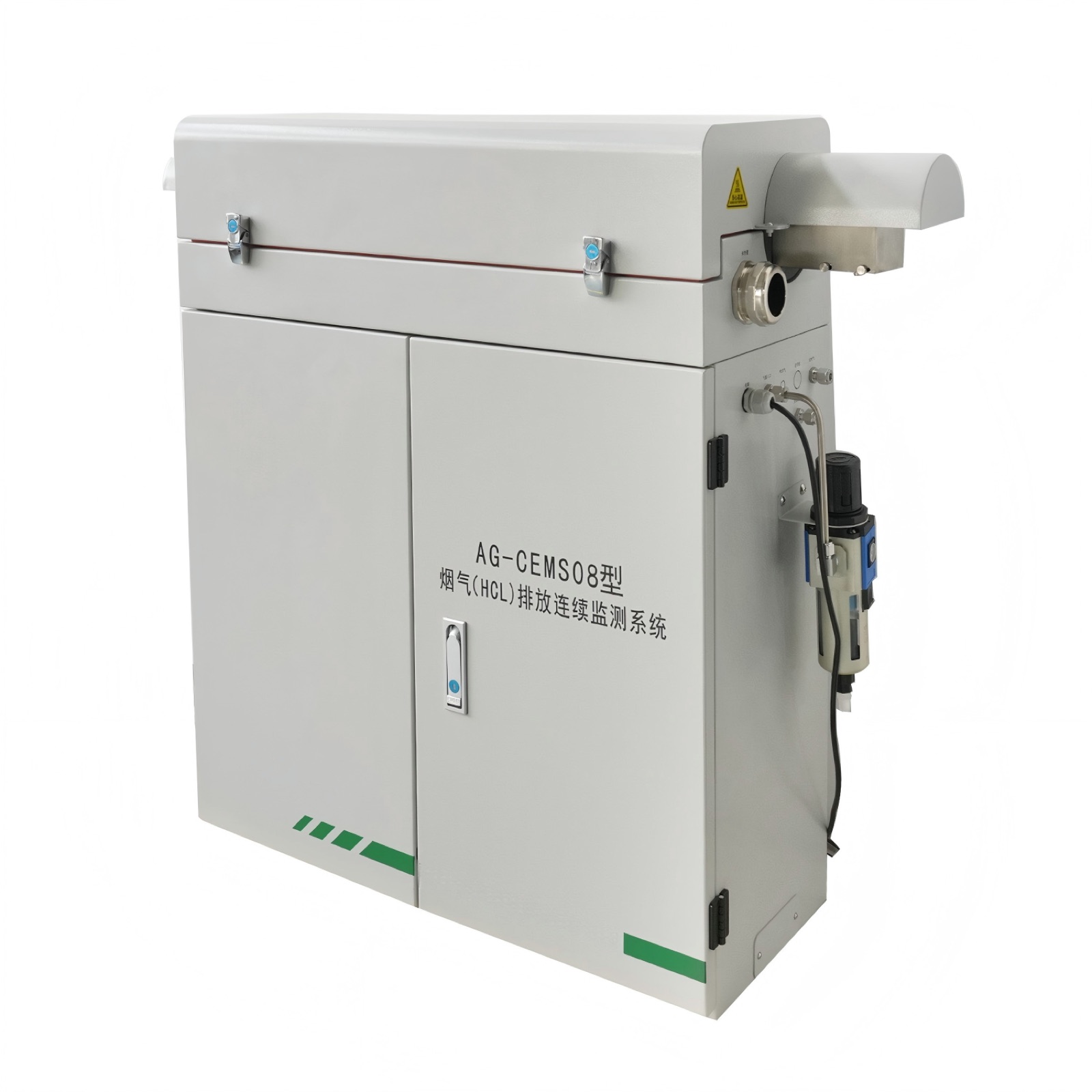
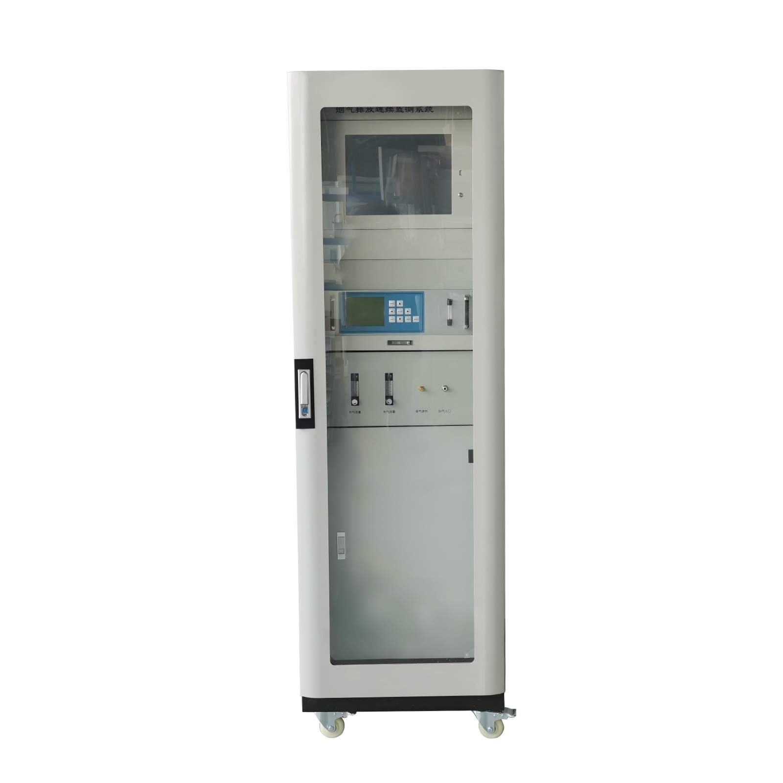
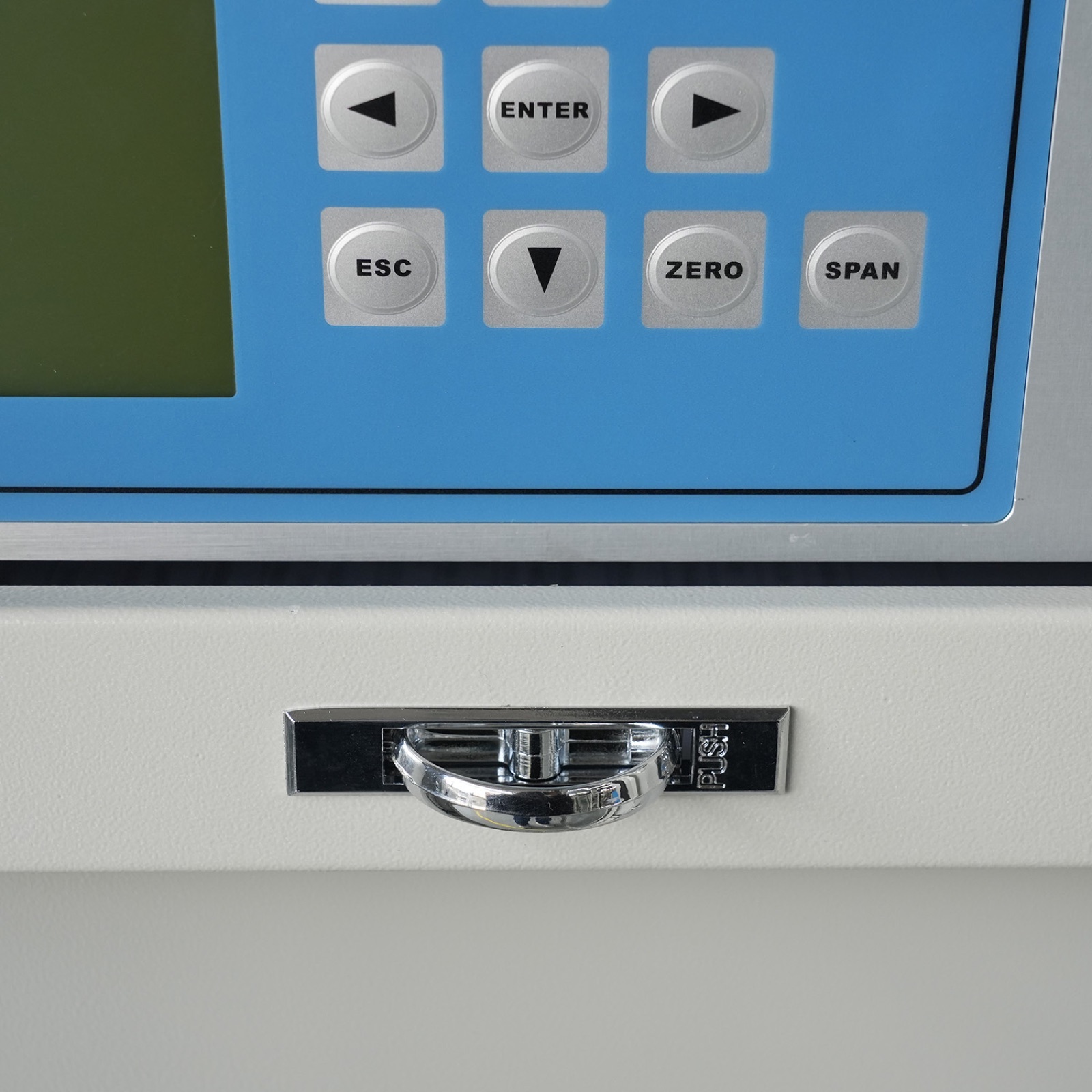
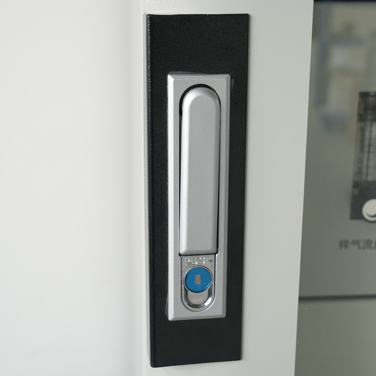
Verified product photos for model review
Additional CEMS, analyzer, dust monitoring and stack-condition product views from Huisheng gas-monitoring materials.