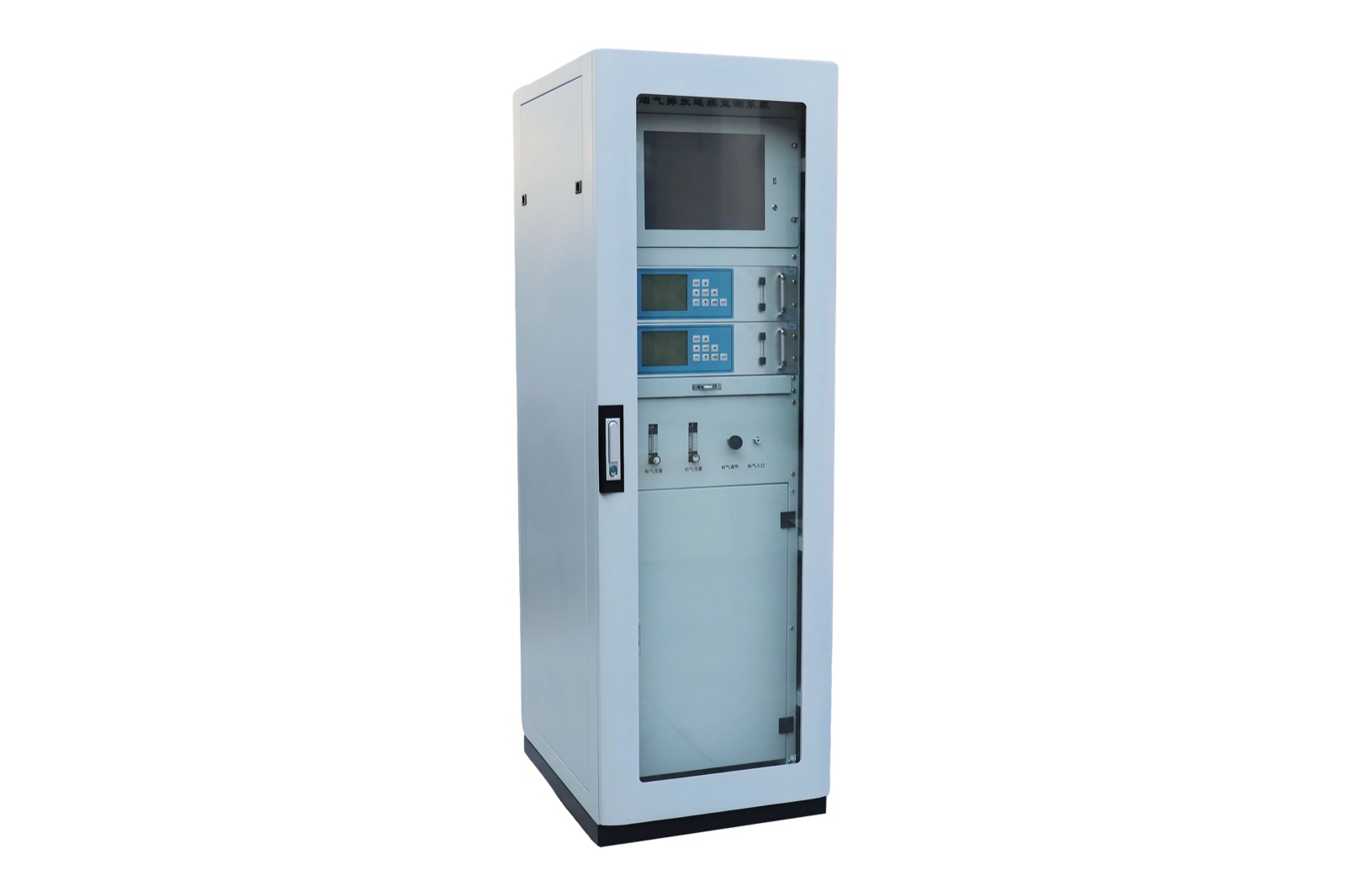
Flue Gas Emission Monitoring System
Emission monitoring equipment for stack gas analysis, particulate measurement and sampling applications.
Flue Gas Emission Monitoring System for environmental monitoring projects
Flue gas emission monitoring equipment for stack gas analysis, particulate measurement and sampling applications.
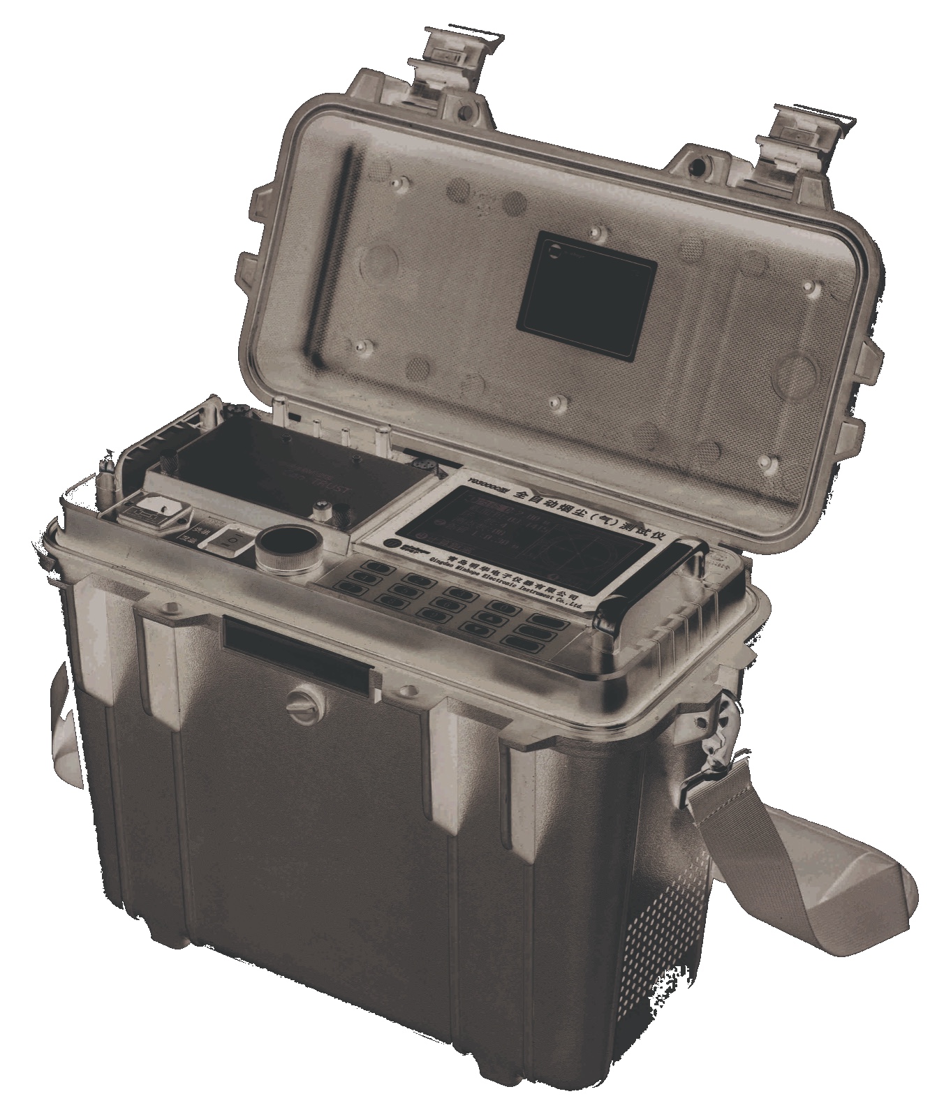
A flue gas emission monitoring system is discussed for industrial stacks, boilers, kilns, furnaces and combustion exhaust points where gas concentration, particulate matter and stack condition indicators must be measured or sampled. It may be a continuous system, a portable testing package or a combination according to project requirements.
The product scope can include gas analyzers, sample probes, heated lines, pretreatment units, particulate testing instruments, flow and temperature measurement, data acquisition and calibration accessories. Stack condition, gas moisture, dust load, acid gas components and platform access shape the final equipment package.
Technical data for model selection
Review the main measuring range, output interface, operating conditions and configuration notes before quotation.
Huisheng confirms the final model, range and site configuration according to sample condition and monitoring requirement.
| Item | Specification / selection note |
|---|---|
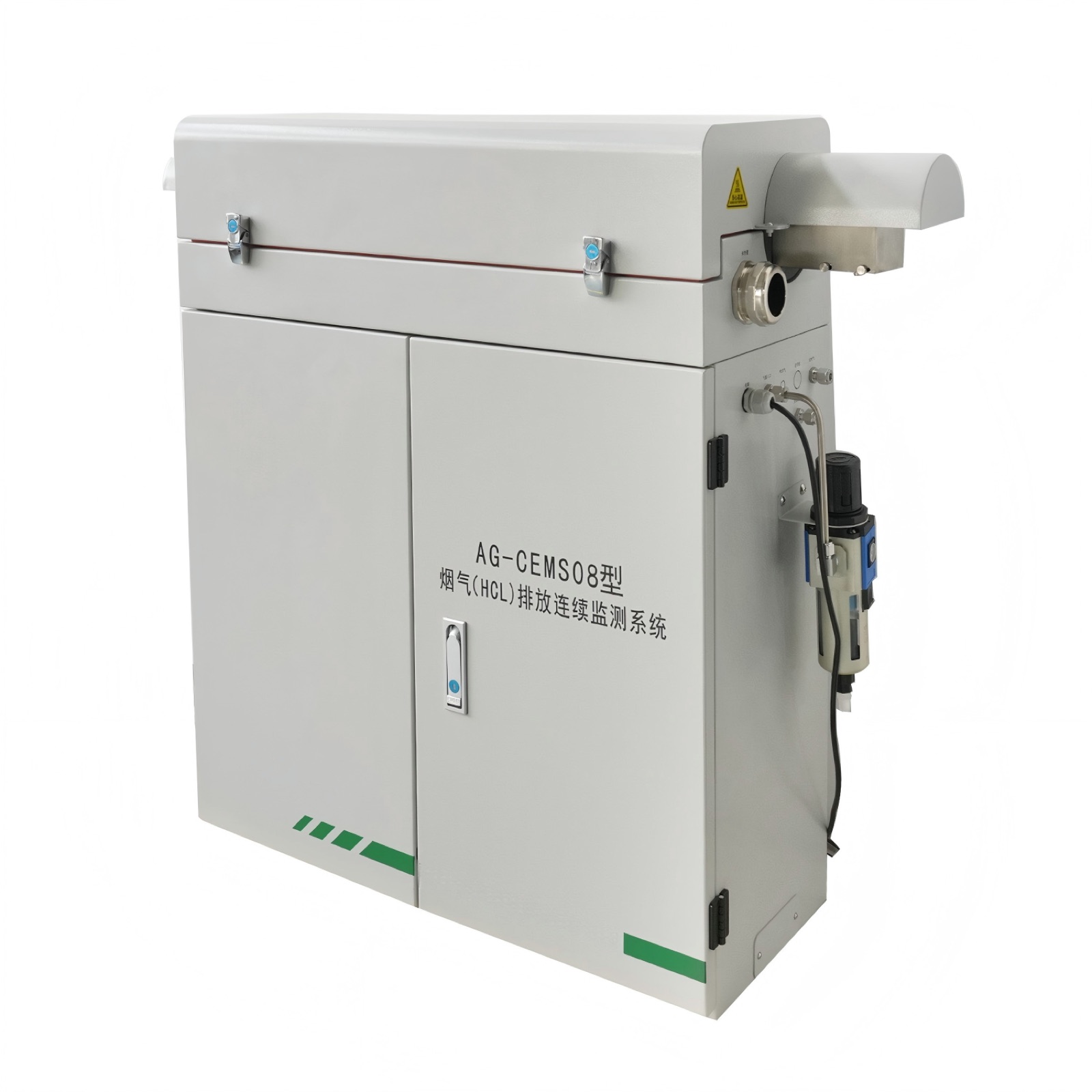
| System | AG-CEMS08 laser pollution-source flue gas continuous emission monitoring analysis system |
| Power | 220VAC, <3kW |
| Purge gas | 0.4-0.6 MPa compressed air |
| Ambient temperature | -20 to 55 degrees C |
| Optical path length | 760 mm |
| Range | 0-100 PPM or mg/m3; adjustable range |
| T90 response time | <300 s |
| Indication error | <= +/-5% nominal value |
| Repeatability | <= +/-2% FS |
| Drift | <= +/-2.5% FS |
| Protection grade | IP55 |
| Output | RS485 digital output; 4-20mA analog output, maximum load 500 ohm |
| Sample gas | Sample gas temperature <600 degrees C; sample gas pressure atmospheric pressure +/-5 kPa; sample flow 2-3 L/min |
| Dimensions / weight | 950H x 1160L x 325W mm; 120 kg |
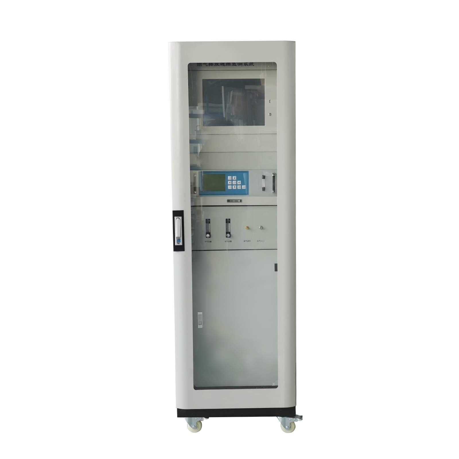
Configured around the actual monitoring point
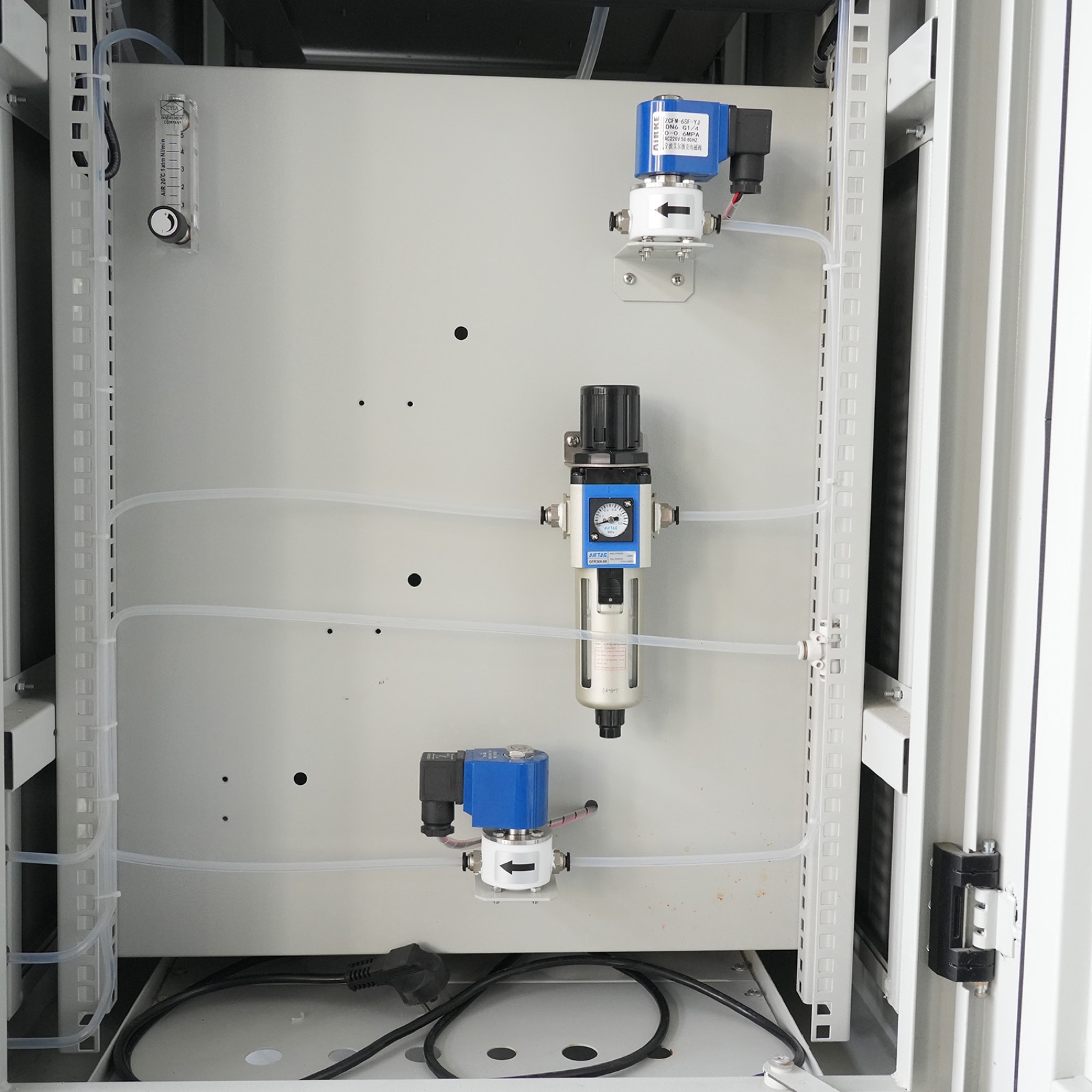
Gas sampling, heated line, pretreatment, analyzer and condition sensors work together as one emission monitoring chain.
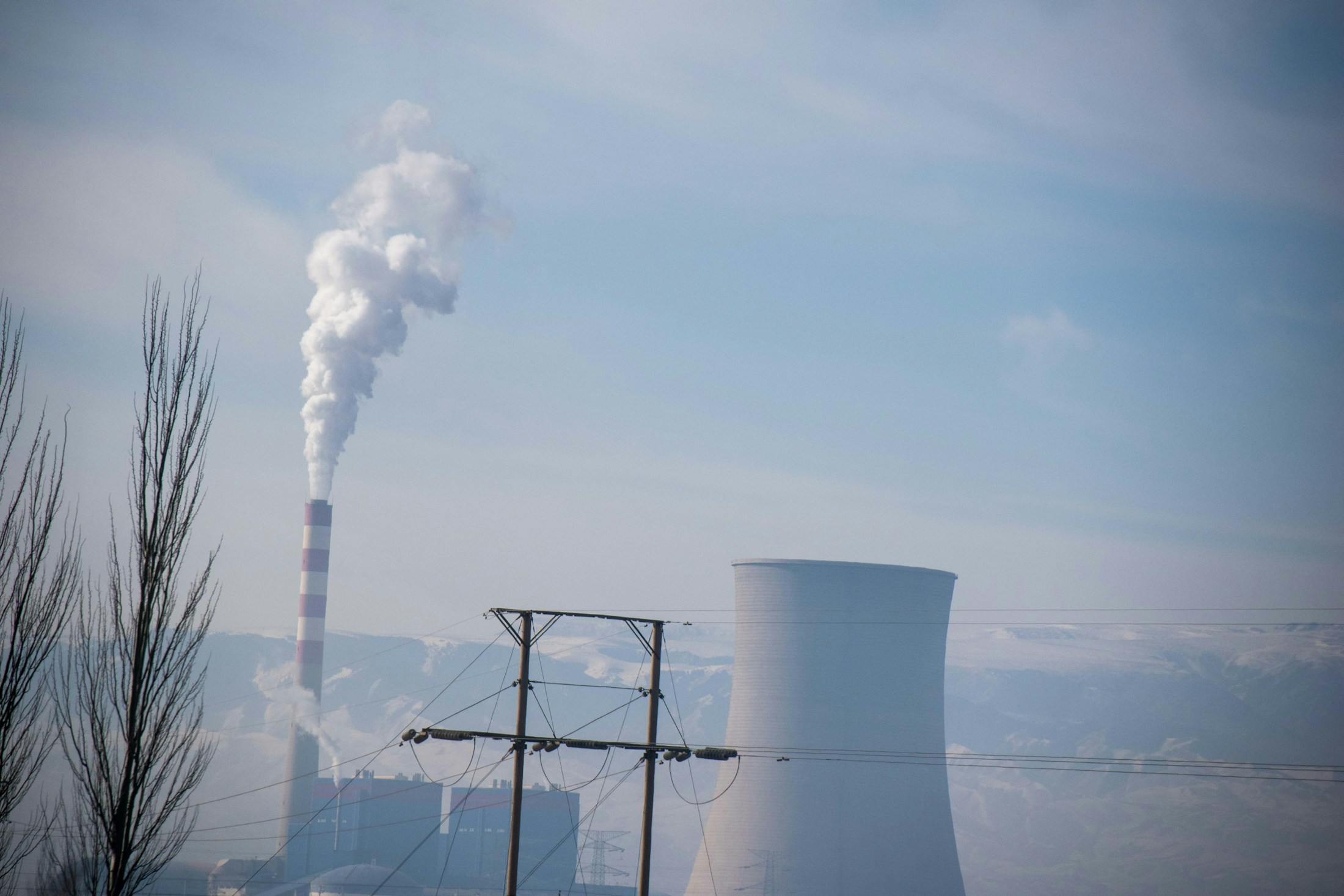
Stack gas, industrial exhaust, combustion flue gas or source emission points
Temperature, moisture, dust, solids, corrosive components or compound type may affect configuration.
Analyzer, detector, sampler, cabinet, pretreatment and data output can be combined as one product package.
Specifications are prepared according to the selected model and actual project requirement.
Details Huisheng reviews before confirming a model
Huisheng reviews the product model together with the measured medium, target range, sampling condition, installation position and required specifications. This keeps the product discussion tied to the real monitoring point.
Expected concentration or detection level helps determine the model and measurement method.
Temperature, moisture, suspended solids, dust, corrosion or target compound behavior may change the configuration.
Gas sampling, heated line, pretreatment, analyzer and condition sensors work together as one emission monitoring chain.
Stack platform, analyzer cabinet, sampling line and data acquisition location
Communication output, alarm logic and model-specific specifications depend on the selected model.
Monitoring indicators covered by this product series
The final parameter package depends on the selected model, measuring range, sample condition and data output requirement. For many projects, one instrument is part of a complete monitoring point rather than a stand-alone purchase.
SO2
Stack gas indicator used for emission source monitoring and reporting.
NOx
Stack gas indicator used for emission source monitoring and reporting.
CO
Stack gas indicator used for emission source monitoring and reporting.
CO2
Stack gas indicator used for emission source monitoring and reporting.
O2
Stack gas indicator used for emission source monitoring and reporting.
Dust
Stack-condition parameter used to interpret emission data and support CEMS configuration.
Flow
Stack-condition parameter used to interpret emission data and support CEMS configuration.
Pressure
Stack-condition parameter used to interpret emission data and support CEMS configuration.
Temperature
Stack-condition parameter used to interpret emission data and support CEMS configuration.
How the product fits into a complete monitoring chain
Most projects connect the product with sample access, conditioning, measurement, data acquisition and reporting. The exact arrangement depends on the site and selected model.
Stack sampling probe
The sample access point determines whether filtration, heating, flow control or preservation is required.
Heated line and pretreatment
This part is configured according to the selected model and actual site conditions.
Gas analyzer or detector
This part is configured according to the selected model and actual site conditions.
Dust and flow measurement
This part is configured according to the selected model and actual site conditions.
Data acquisition and reporting interface
Data acquisition, alarm output and communication must match the project platform or reporting requirement.
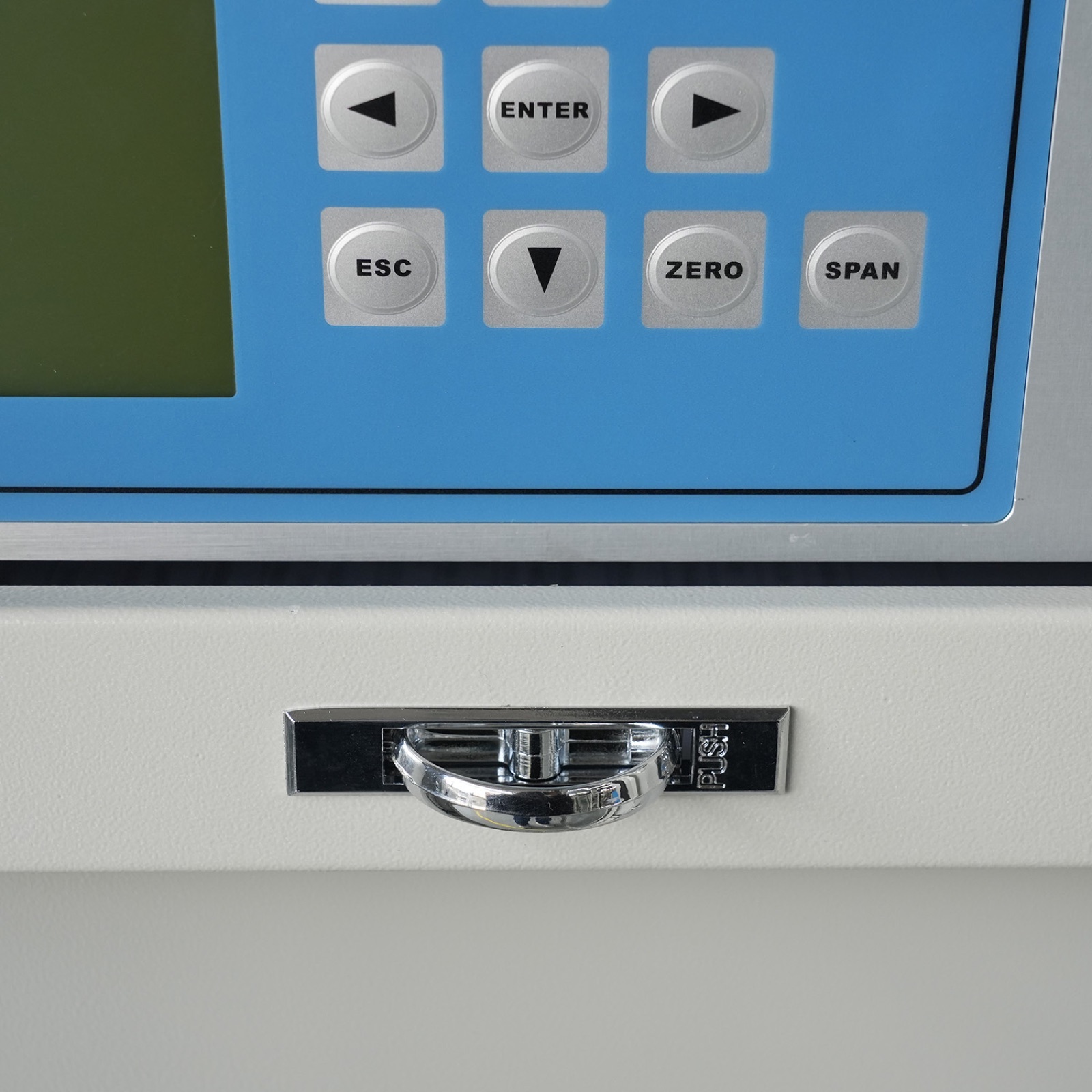
Where this equipment is usually discussed
Emission applications depend on the stack or duct condition. Gas temperature, dust load, moisture, sampling platform and reporting purpose all influence the analyzer, sampler or complete CEMS configuration.
Applied at fixed emission sources where sample extraction, condition measurement and reporting output must work as one chain.
Applied at fixed emission sources where sample extraction, condition measurement and reporting output must work as one chain.
Selected when representative field collection, controlled flow and later analysis are part of the monitoring method.
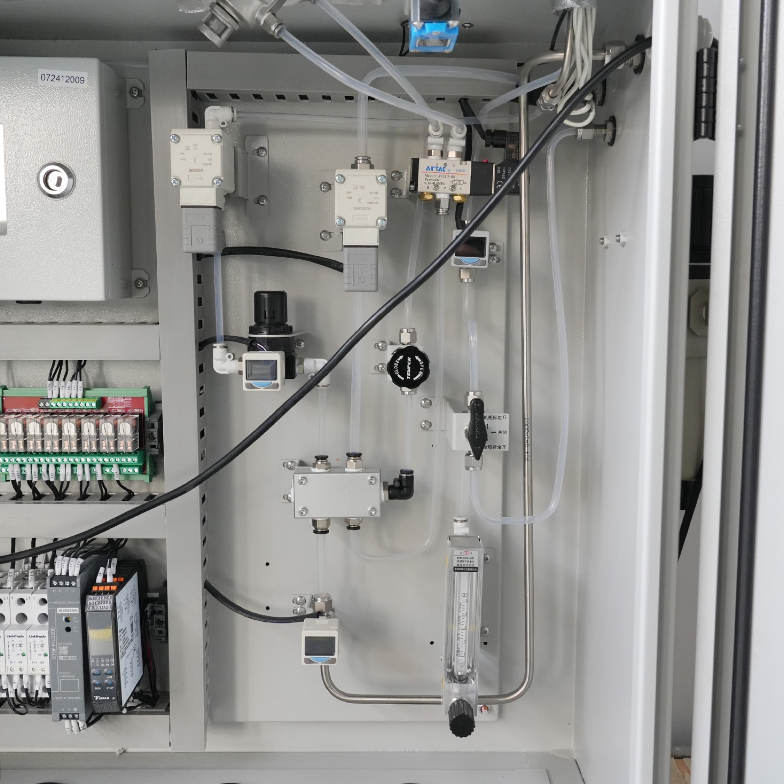
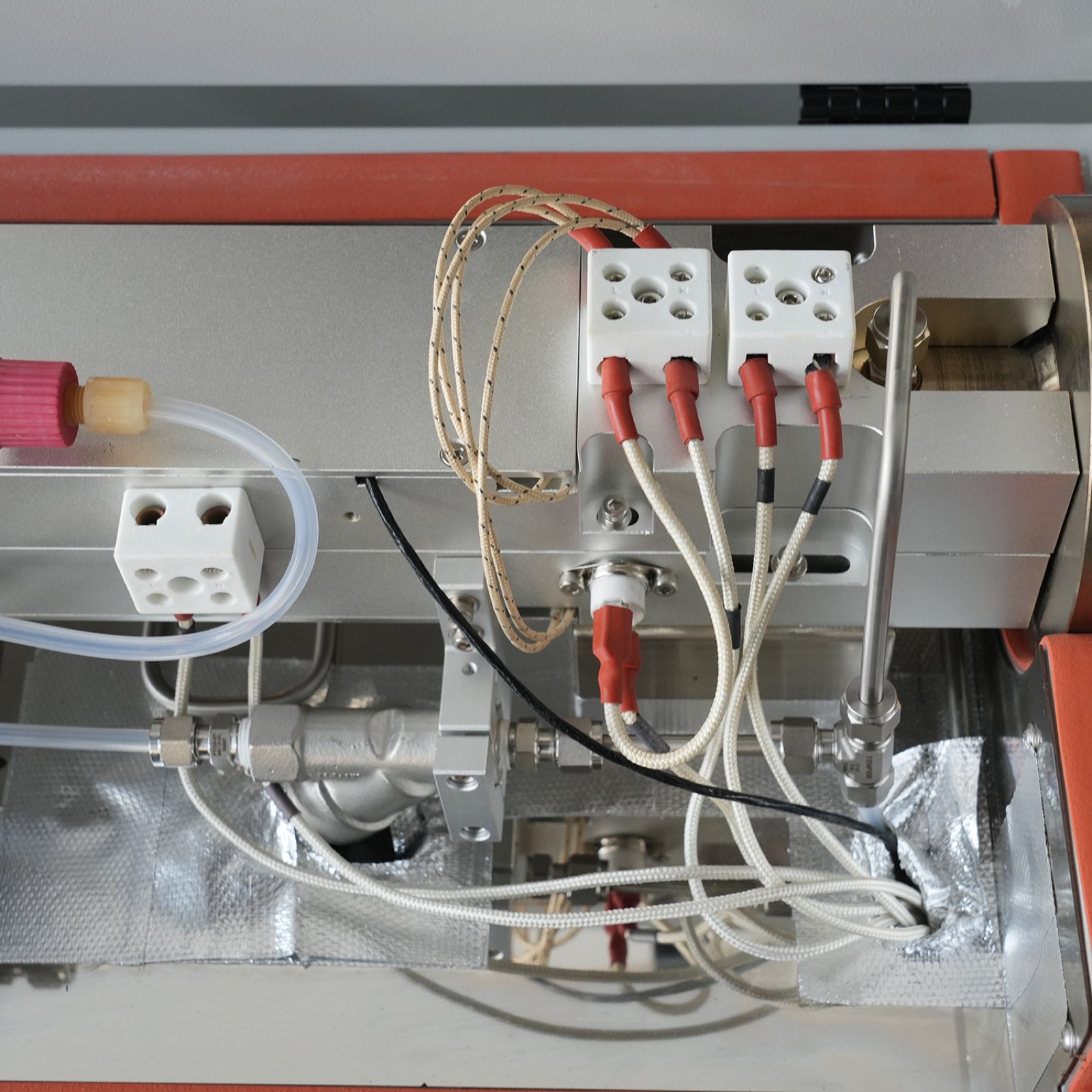
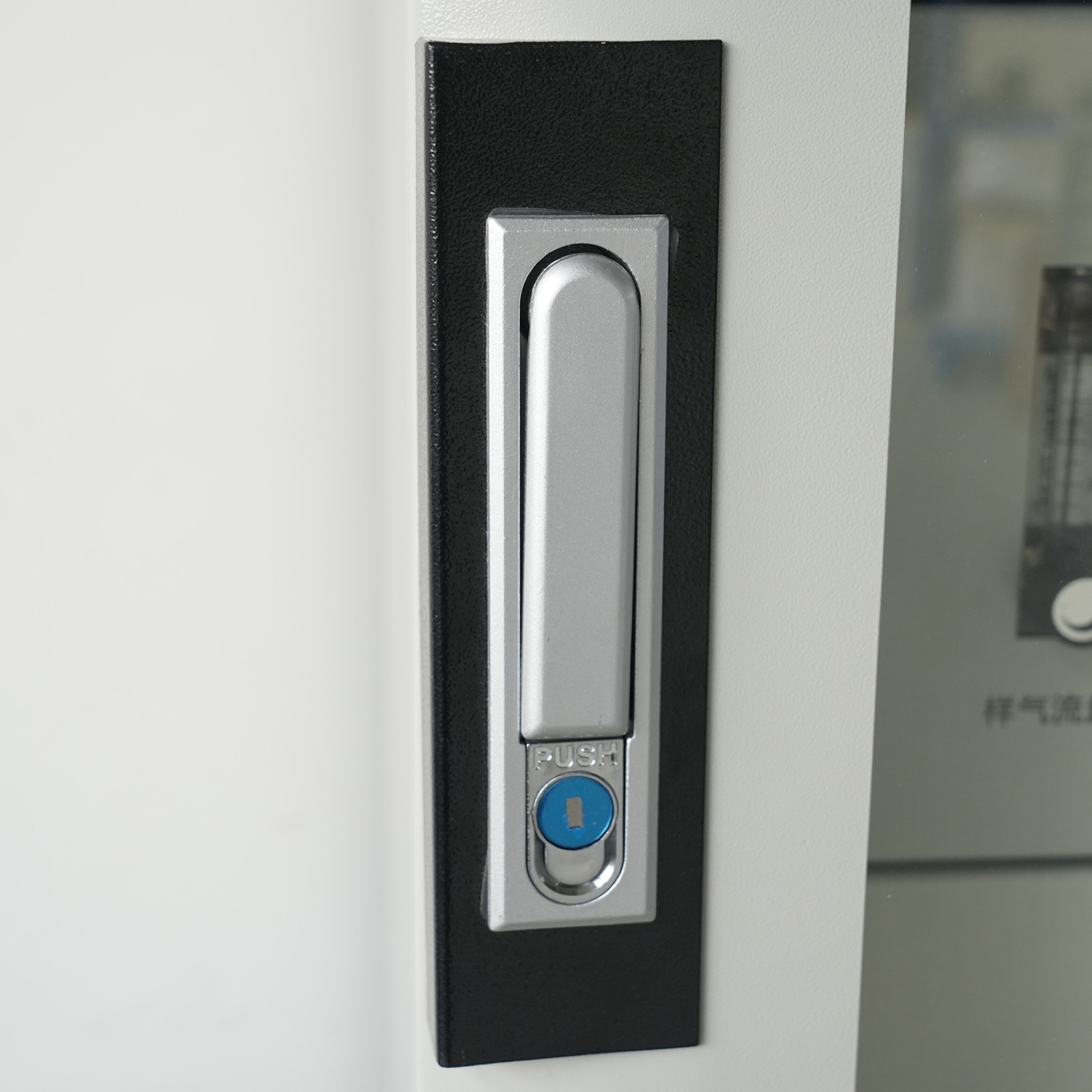
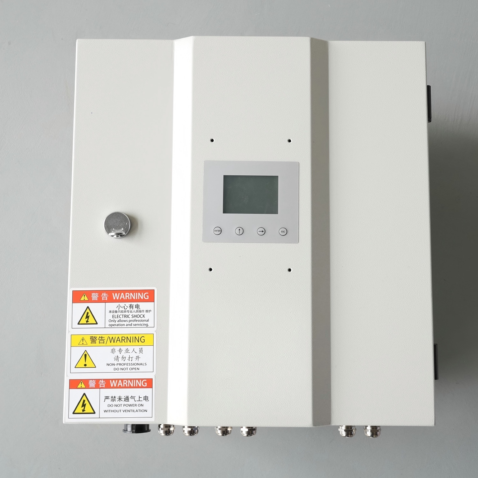
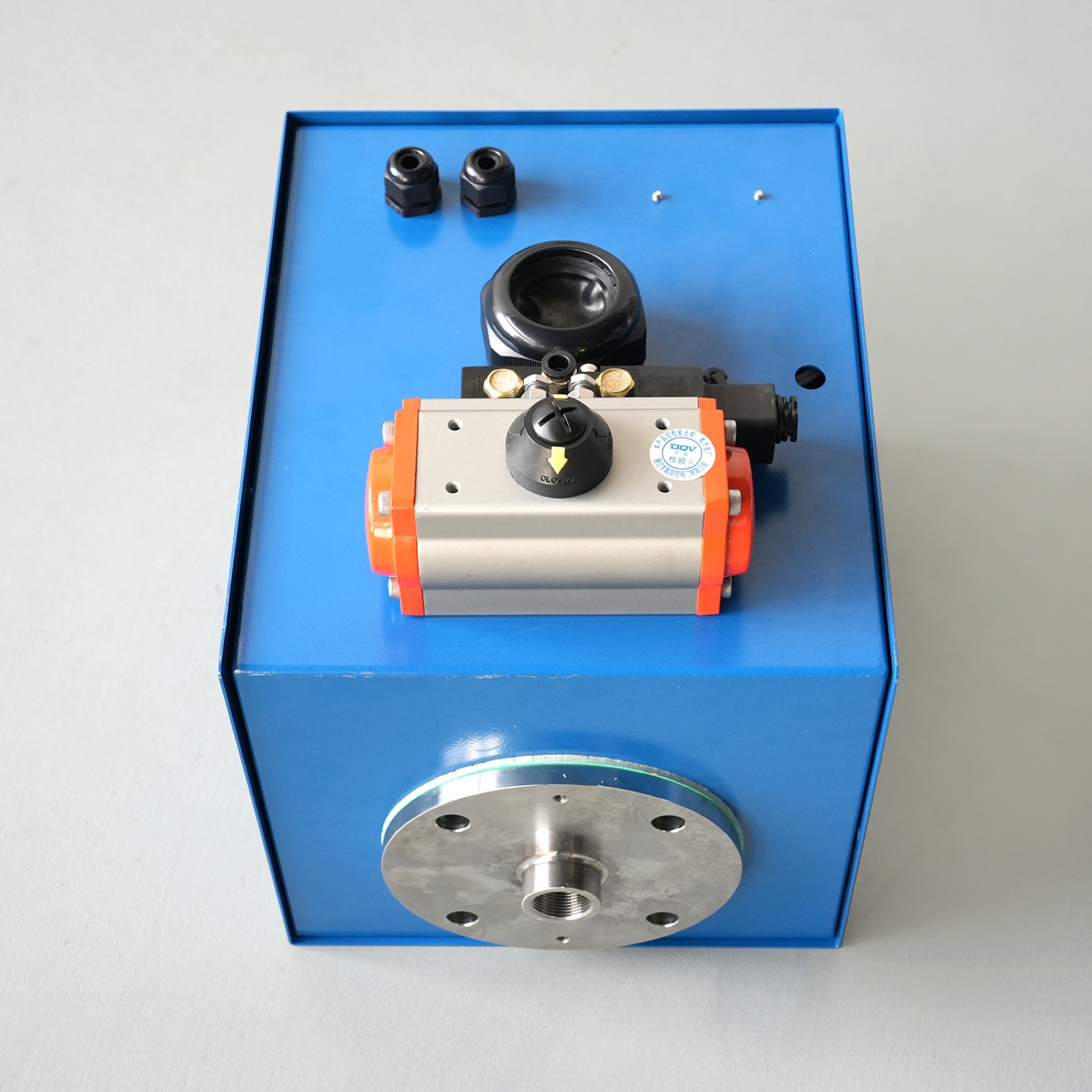
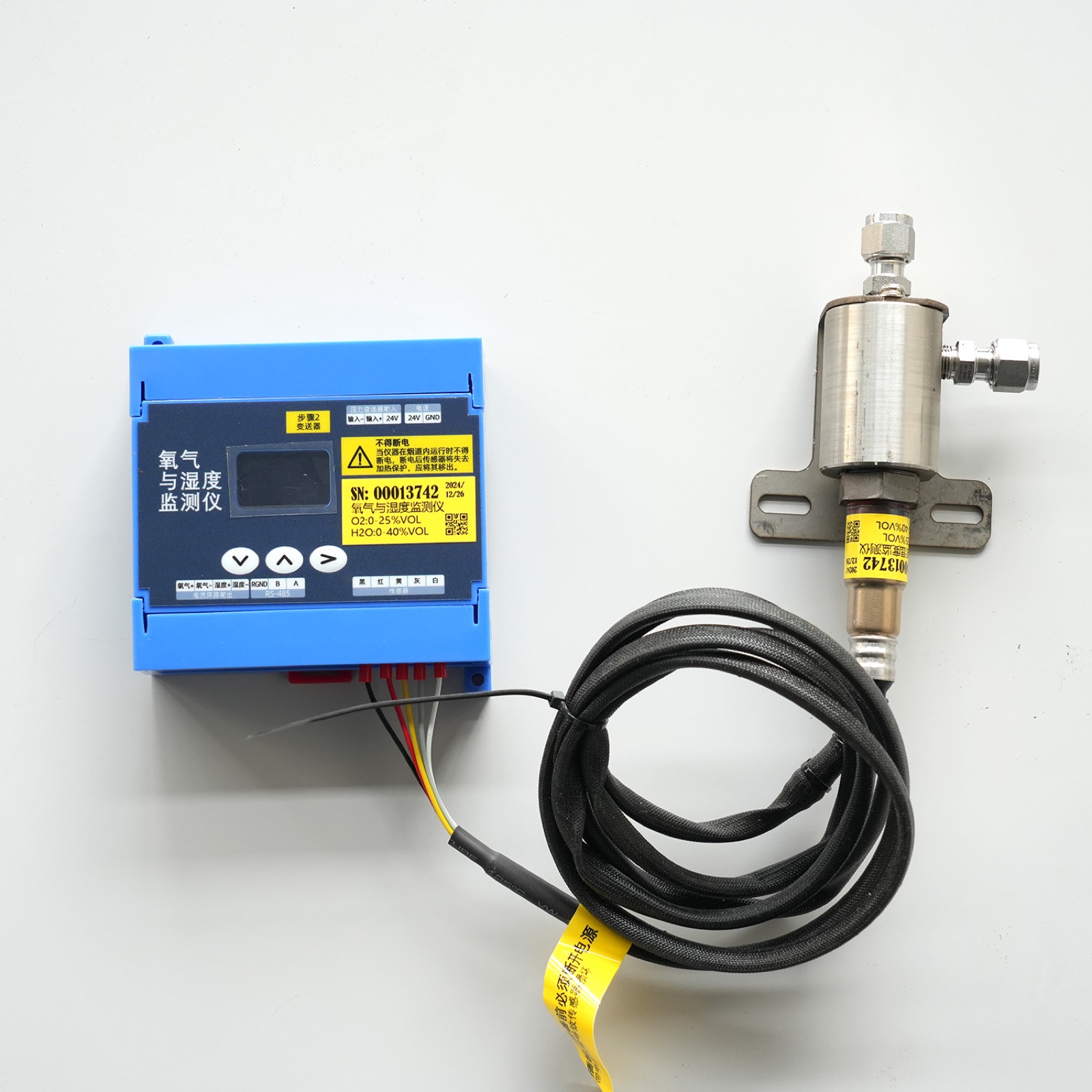
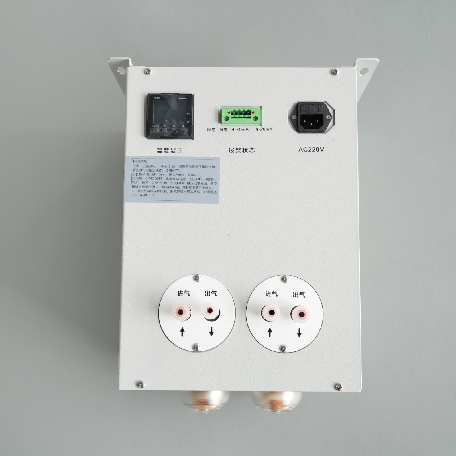
Verified product photos for model review
Additional CEMS, analyzer, dust monitoring and stack-condition product views from Huisheng gas-monitoring materials.