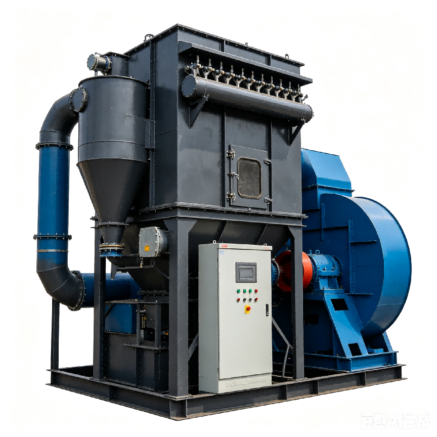
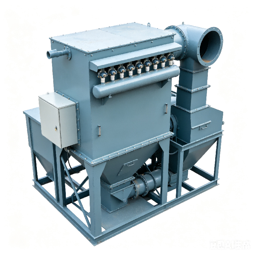
Wet Electrostatic Precipitator
Wet electrostatic precipitator for deep dust, mist and aerosol removal in ultra-low emission flue gas treatment projects.
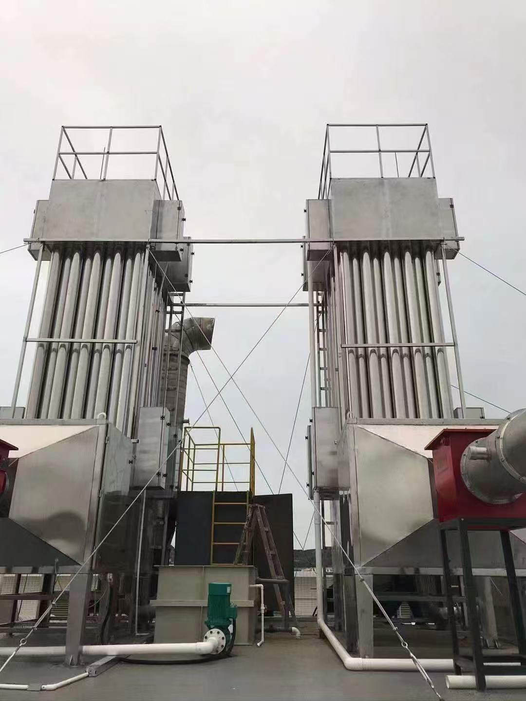
Wet Electrostatic Precipitator for pollution-control projects
Wet electrostatic precipitator for deep removal of fine dust, acid mist, tar mist and wet flue gas aerosols after desulfurization or high-humidity treatment sections.
Wet electrostatic precipitator equipment is discussed when ordinary bag filtration or spray washing is not enough for fine dust, acid mist, tar mist or high-humidity flue gas polishing.
The WESP document lists air volume from 5000 to 150000 m3/h, dust and mist removal efficiency >=99%, outlet dust <=5 mg/m3, operating resistance around 300-600 Pa and DC high-voltage power supply around 30-80 kV.
Equipment data from supplied material
This table keeps the equipment values, routes and material options stated in the supplied product material. Selection notes and related-product links elsewhere on the page are website guidance, not added hard specifications.
Supplied wet electrostatic precipitator performance material. Final sizing still depends on site conditions, but the values in this table are kept to the supplied material.
| Item | Specification / selection note |
|---|---|
| Typical air volume | 5000-150000 m3/h; customization supported |
| Dust / mist removal efficiency | >=99% listed in the document |
| Outlet dust target | <=5 mg/m3 listed in the document |
| Operating resistance | 300-600 Pa |
| Working temperature | <=180 deg C |
| High-voltage power supply | 30-80 kV DC high-voltage power supply |
| Washing method | Continuous water-film spray plus intermittent plate flushing |
| Typical process route | Boiler flue gas -> SCR denitrification -> bag dust collector -> wet desulfurization tower -> WESP -> stack |
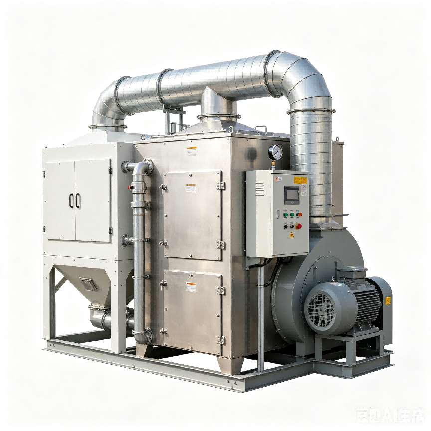
Configured around the actual treatment route
The treatment route is confirmed from the supplied equipment material, then sized by air volume, water volume, pollutant type, material requirement and site layout.
Project-specific wastewater, exhaust gas or pollution control applications
Air volume, water volume, pollutant type, temperature, humidity, corrosion and inlet condition affect configuration.
Treatment body, fans, ducts, pumps, control cabinet, safety protection and maintenance access are reviewed by route.
Hard parameters are kept to supplied product material; final sizing is confirmed by project condition.
Selection notes kept separate from source parameters
Huisheng reviews the treatment route, handled medium, capacity, material, outlet target and auxiliary systems before confirming a configuration. Documented values remain in the technical data table, while project pairing and monitoring-interface notes are treated as selection guidance.
Hard values are kept to the supplied product material. Project-specific sizing is treated as selection work, not as a new published parameter.
Exhaust gas, dust, odor, flue gas polishing or wastewater condition should be confirmed before choosing the treatment route.
Air volume, water volume, pollutant load and outlet requirement determine final equipment sizing.
Q235, 304 stainless steel, FRP, PP or anti-corrosion options are selected according to the documented material scope and site condition.
Fans, ducts, pumps, control cabinets, safety protection and monitoring interfaces are discussed as configuration notes.
Parameters and scope stated in supplied material
The items below summarize capacity, material, process route, efficiency or equipment-scope information from the supplied product material. Extra project advice stays in selection notes instead of becoming a published hard parameter.
5000-150000 m3/h
Documented WESP air-volume range for large flue-gas polishing projects.
>=99% dust / mist removal
Removal efficiency listed for fine dust, acid mist and aerosol polishing.
<=5 mg/m3 outlet dust
Outlet dust target stated for ultra-low-emission discussion.
300-600 Pa
WESP operating resistance range used for system pressure review.
30-80 kV DC
High-voltage DC power supply range for the electrostatic field.
WESP
Wet electrostatic polishing route for humid flue gas, mist, tar and fine particles.
How the equipment fits into a treatment route
Treatment equipment is configured by process route, pollutant type, air or water volume, material requirement and installation condition. Monitoring or sampling interfaces are considered only when the project needs them.
Gas distribution inlet section
The sample access point determines whether filtration, heating, flow control or preservation is required.
High-voltage electric field
This part is configured according to the selected model and actual site conditions.
Anode tube bundle
This part is configured according to the selected model and actual site conditions.
Cathode discharge electrodes
This part is configured according to the selected model and actual site conditions.
Spray and flushing system
This part is configured according to the selected model and actual site conditions.
Bottom water collection tank and control system
This part is configured according to the selected model and actual site conditions.
Where this equipment is usually discussed
This equipment is discussed when the project needs monitoring or supporting treatment equipment matched with the actual site, medium, parameter and reporting requirement.
Applied at fixed emission sources where sample extraction, condition measurement and reporting output must work as one chain.
Discussed as supporting equipment when pollution control and monitoring requirements are reviewed in the same project.
Discussed as supporting equipment when pollution control and monitoring requirements are reviewed in the same project.
Used around process areas, storage zones and boundary points where VOC or hazardous gas monitoring is required.
Discussed as supporting equipment when pollution control and monitoring requirements are reviewed in the same project.